Graphical models can take many forms, but their prime function is always the same—to simplify the data and present it in such a way that understanding of what is being presented aids further development or discussion. Designers utilize graphical modelling as a tool to explore creative solutions and refine ideas from the technically impossible to the technically possible, widening the constraints of what is feasible.
A graphical model is a visualization of an idea, often created on paper or through software. Graphical models are used to communicate with oneself and others which include design team members, the client an the manufacturer. The architect would use plans (orthographic) for the builders but perspective for the client.
2D Graphical Models
|
|
|
|
|
|

3D Graphical Models
|
|
 |
 |
|


Perspective, Projection and Scale drawings
Term: Projection Drawings – Systems of drawings that are accurately drawn, the two main types are isometric projection (formal drawing technique) and orthographic projection (working drawing technique).
Term: Scale Drawings – Drawings that are bigger or smaller than the real product, but exactly in proportion with product.
Term: Working Drawings – Drawings that are used to guide the production of a product, most commonly orthographical projection, section drawings, part drawings, assembly drawings and plan drawings.
Orthogonal/Orthographic Drawings/Projections
|
|
- A series of flat (2D) views of an object showing it exactly as it is in shape and size i.e. constructional details.
- An orthographic drawing shows all details and dimensions and is usually used as a production/working drawing.
- It is a convergent thinking style of drawing.
- Orthographic drawings are produced at the final solution stage and are used as working drawings in the realization stage.
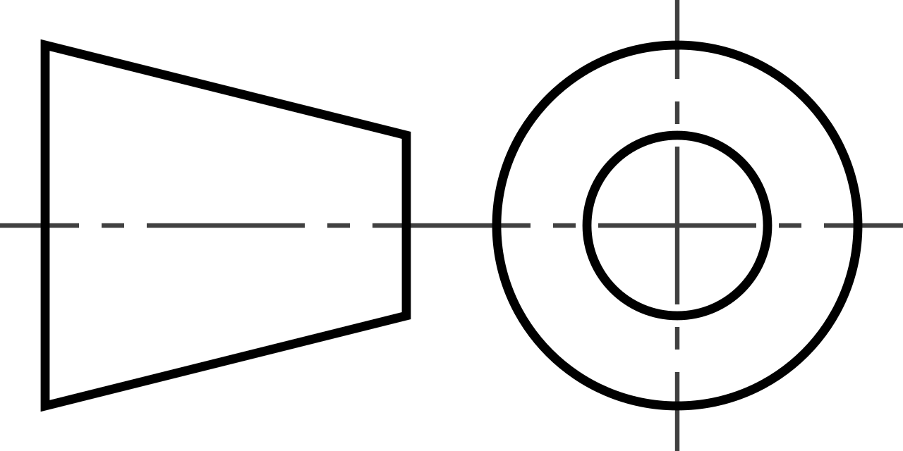
3rd Angle Projection - International conventions need to be used, such as, 3rd Angle projection, ISO, scale, units, etc which will be explained in criterion C.

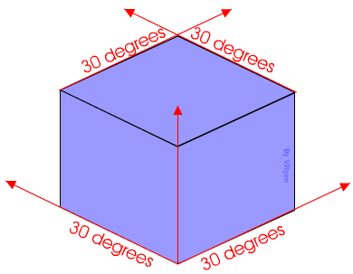
Isometric Drawing/Projection.
- An isometric drawing depicts the proposed solution in 3D showing shape and form.
- They are drawn on a 30/90/30 degree axis.
- More on isometric drawings (projections).
|
|
|
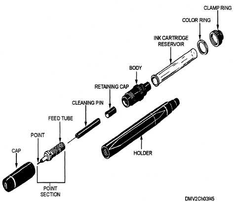
Exploded Isometric Drawing.
- An isometric drawing of an object with more than one component that depicts how the parts of assemblies fit together.
- The drawing is exploded to show component parts of a product and/or the sequence of assembly.
- Isometric drawings are produced at the final solution stage and are used as working drawings in the realization stage
|
|
|

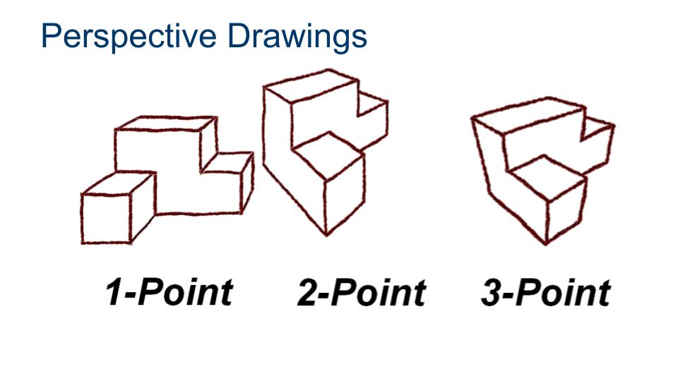
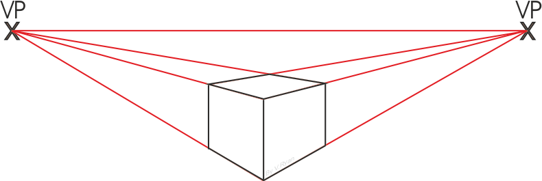
Perspective drawing
Term: A set of formal drawing techniques that depicts an object as getting smaller and closer together the further away they are. The techniques are one-point perspective, two-point perspective, and three-point perspective.
| One Point | Two Point | Three Point |
|
|
 |
 |
|
|
|
|
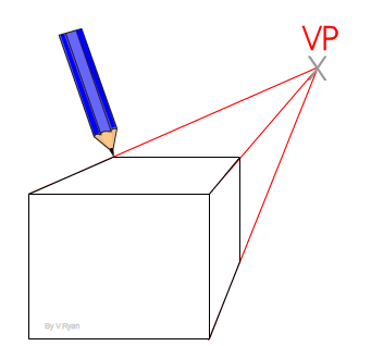
- A 3D drawing that realistically represents an object by utilizing foreshortening and vanishing points (usually imaginary ones).
- Comparison of perspective drawings with isometric drawings …
- Perspective drawings take into account spatial arrangements, for example, foreshortening, while isometric drawings are constructed to a set angle.
- Can be used in the planning stages to communicate what it might look like.
- Good for clients who may not understand orthographic or isometric drawings.
Assembly and Parts Drawing
Term: Assembly Drawing – A diagram that shows how components fit together to make a whole.drawings Typically presented in an exploded view.
Assembly drawings show how different parts [components] go together, identify those parts by number, and have a parts list, often referred to as a bill of materials.
Term: Parts (Component) Drawing – Orthographic drawings of the components of an assembly containing details just about that component.
Is a part/component of a a product that is assembled with other components and/or sub assemblies.
|
|
|


Sketching versus Formal Drawing Techniques
Term: Sketches – Rough drawings of ideas used to convey or refine the idea.
Term: Formal drawing techniques – A type of drawing technique that has fixed rules, the most widely used being isometric projection and perspective drawing.
| Activity: What things have caught your attention in this video? | |
| Activity: What things have caught your attention in this video compared to the freehand sketching one? |
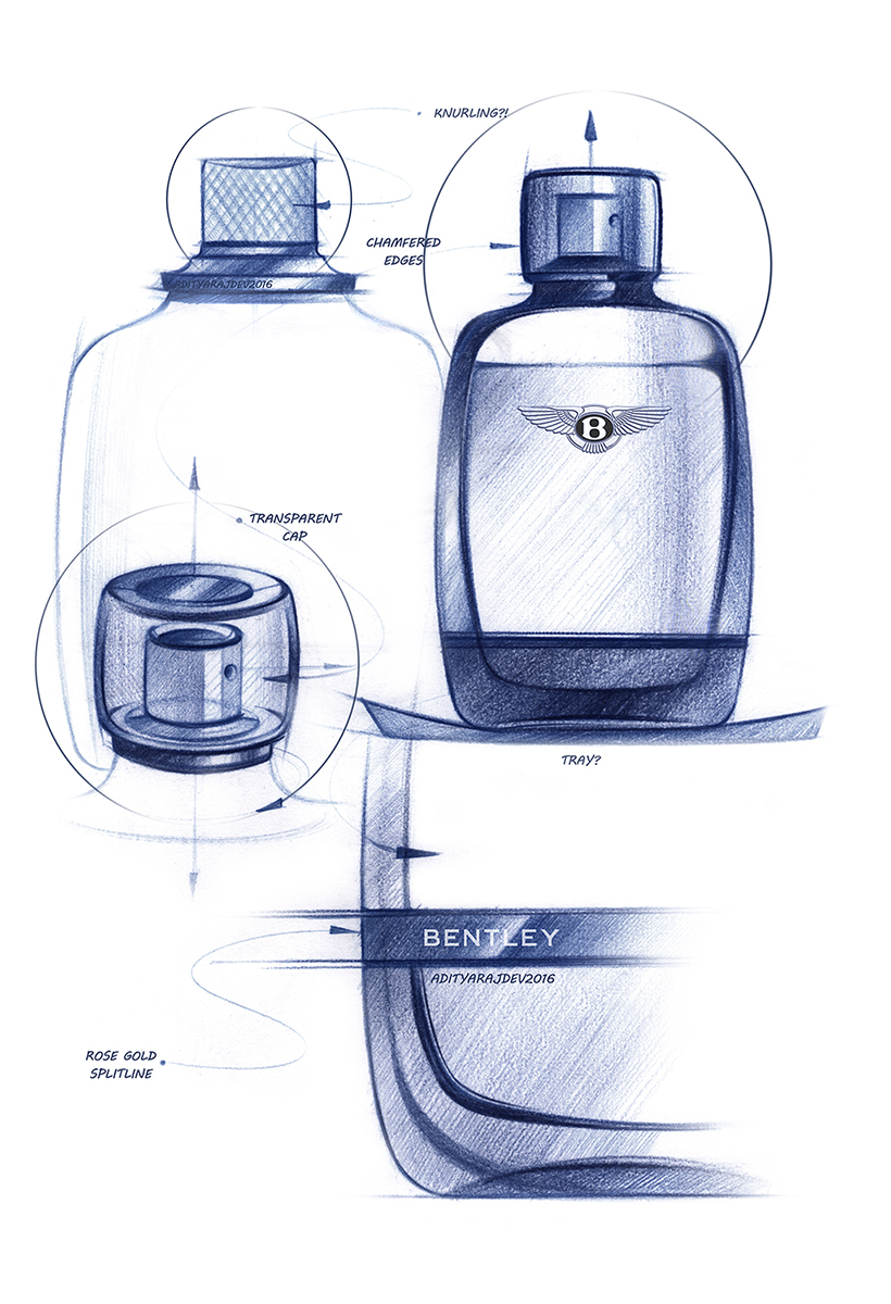
Sketching or freehand drawings
- Are spontaneous representation of ideas on paper without the use of technical aids.
- Designers use a range of freehand drawings in the early stages of developing ideas to explore shape and form (3D) and constructional details (2D).
- Divergent thinking is prominent at this stage.
Annotations
- Explain the thinking behind the visual image represented by the drawing.
- They allow the designer to consider the implications of the ideas for further development.
- Annotated drawings are an alternative form of expression of ideas that allows one to indicate links between the ideas.
Formal drawings.
- Include: orthogonal, isometric, exploded isometric, sectional, parts and assembly drawings which are done with great precision and usually with mechanical drawing aides (ruler, square, compass) or in CAD programs (Autodesk Fusion).
- Designers use these drawings at the realisation/development stage where the product is to be made. They are used to communicate to the manufacturer.
- Convergent thinking is prominent at this stage.
Advantages and Disadvantages
| Type of Model | Advantages | Disadvantages |
| Orthogonal |
|
|
| Isometric |
|
|
| Perspective |
|
|
| Assembly |
|
|
| Freehand |
|
|
Theory of Knowledge:
Are there aspects of the world that are not amenable to modeling?
To what extent does graphical communication shape and limit our knowledge?